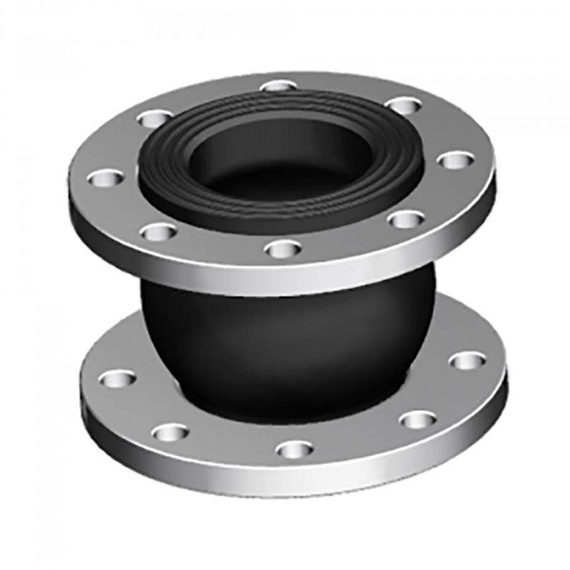
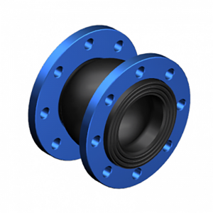
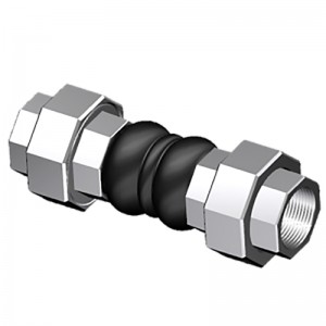
Supply OEM China High Temperature EPDM Flexible Single Sphere Rubber Expansion Joints with Flange
We now have our individual sales group, layout team, technical team, QC crew and package group. Now we have strict high-quality control procedures for each procedure. Also, all of our workers are experienced in printing discipline for Supply OEM China High Temperature EPDM Flexible Single Sphere Rubber Expansion Joints with Flange, Safety by means of innovation is our promise to each other.
We now have our individual sales group, layout team, technical team, QC crew and package group. Now we have strict high-quality control procedures for each procedure. Also, all of our workers are experienced in printing discipline for China Rubber Bellow, Flexible Rubber Joint, Our company covers an area of 20, 000 square meters. We have now more than 200 workers, qualified technical team, 15 years’ experience, exquisite workmanship, stable and reliable quality, competitive price and sufficient production capacity, this is how we make our customers stronger. If you have any inquiry, make sure you do not hesitate to contact us.
Details
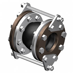
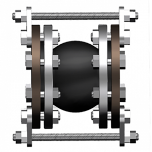
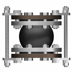
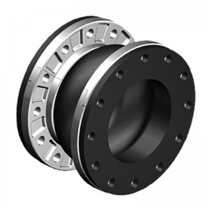
The single-arch product can reduce the vibration and noise, which can also solve the axial/lateral/angular movements/eccentric problems. Reinforcement layer of the bellows by Nylon cords and at both ends by hardened steel wire rings. The floating steel flanges are drilled according to DIN, ANSI, BS, JIS and other standards. If the piping pressure is much higher, reinforced bolts should be assembled together with flanges.
| Specifications | I | II | III |
| Working Pressure Mpa (Kgf/Cm2) | 1Mpa (10) | 1.6 (16) | 2.5 (25) |
| Test Pressure | 1.5Mpa | 2.4Mpa | 3.75Mpa |
| Burst Pressure Mpa (Kgf/Cm2) | 3 (30) | 4.8 (48) | 5.5 (55) |
| Vacuum Kpa (Kgf/Cm2) | 53 (400) | 86(660) | 100 (750) |
| Materials | EPDM/NBR/SBR/NR | ||
| Diameter Range | DN15-DN600 (1/2″-24″) | ||
| Connection Method | FLANGETHREADCLAMP | ||
| Flanges Dimensions | DIN, EN,ANSI, BS, JIS and other standards | ||
| Applicable Medium | Air, compressed air, water, seawater, hot water, oil, acid, alkali etc. | ||
| Loading Port: | Qingdao, China | ||
| Shipment Terms: | FOB, CFR, CIF | ||
| Production Capacity: | 50000 set | ||
| Payment Terms: | L/C, T/T, D/P | ||
| Connection: | Flange, Thread | ||
| Flange Material: | Carbon Steel, Stainless Steel | ||
| Period of Delivery | about 21 working days | ||
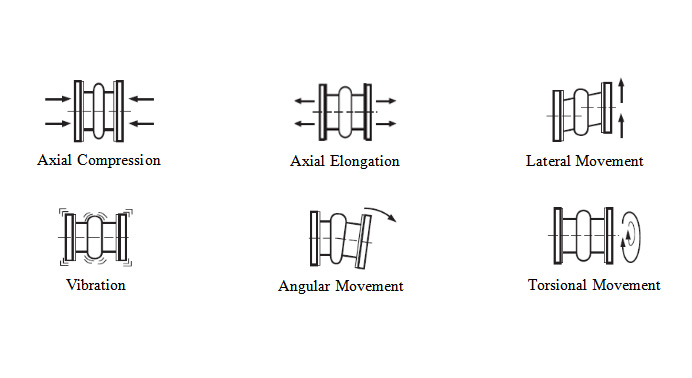
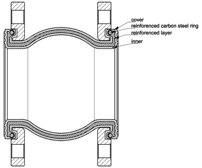
|
Single Arch-Standard Length |
||||||||
|
Dimensions |
Movement Distance |
Operating Condition |
||||||
|
Pipe Size |
Standard O’all Length |
Axial Compression |
Axial Extension |
Lateral Deflection |
Angular Deflection |
Max w.p. bar(psi) |
Max Vacuum (mm hg) / Kmpa |
|
|
Inch |
mm |
mm |
mm |
mm |
mm |
|||
|
1 1/4″ |
32 |
95 |
10 |
6 |
10 |
25° |
16(225) |
700(86Kpa) |
|
1 1/2″ |
40 |
95 |
10 |
6 |
10 |
25° |
16(225) |
700(86Kpa) |
|
2″ |
50 |
105 |
10 |
6 |
10 |
25° |
16(225) |
700(86Kpa) |
|
2 1/2″ |
65 |
115 |
15 |
8 |
12 |
25° |
16(225) |
700(86Kpa) |
|
3″ |
80 |
135 |
15 |
8 |
12 |
25° |
16(225) |
700(86Kpa) |
|
4″ |
100 |
135 |
20 |
12 |
16 |
15° |
16(225) |
700(86Kpa) |
|
5″ |
125 |
165 |
20 |
12 |
16 |
15° |
16(225) |
700(86Kpa) |
|
6″ |
150 |
180 |
20 |
12 |
16 |
15° |
16(225) |
700(86Kpa) |
|
8″ |
200 |
205 |
20 |
12 |
16 |
15° |
16(225) |
700(86Kpa) |
|
10″ |
250 |
240 |
30 |
14 |
25 |
8° |
16(225) |
700(86Kpa) |
|
12″ |
300 |
260 |
30 |
14 |
25 |
8° |
16(225) |
700(86Kpa) |
|
14″ |
350 |
265 |
30 |
14 |
25 |
8° |
16(225) |
700(86Kpa) |
|
16″ |
400 |
265 |
30 |
14 |
25 |
8° |
16(225) |
700(86Kpa) |
|
18″ |
450 |
265 |
30 |
14 |
25 |
8° |
16(225) |
700(86Kpa) |
|
20″ |
500 |
265 |
30 |
14 |
25 |
8° |
16(225) |
700(86Kpa) |
|
24″ |
600 |
265 |
30 |
14 |
25 |
8° |
16(225) |
700(86Kpa) |
|
Single Arch-130MM |
||||||||
|
Dimensions |
Movement Distance |
Operating Condition |
||||||
|
Pipe Size |
Special O’all Length |
Axial Compression |
Axial Extension |
Lateral Deflection |
Angular Deflection |
Max w.p. bar(psi) |
Max Vacuum (mm hg) / Kmpa |
|
|
Inch |
mm |
mm |
mm |
mm |
mm |
|||
|
1 1/4″ |
32 |
130 |
30 |
20 |
20 |
35° |
16(225) |
660(26) |
|
1 1/2″ |
40 |
130 |
30 |
20 |
20 |
35° |
16(225) |
660(26) |
|
2″ |
50 |
130 |
30 |
20 |
20 |
35° |
16(225) |
660(26) |
|
2 1/2″ |
65 |
130 |
30 |
20 |
20 |
30° |
16(225) |
660(26) |
|
3″ |
80 |
130 |
30 |
20 |
20 |
30° |
16(225) |
660(26) |
|
4″ |
100 |
130 |
30 |
20 |
20 |
25° |
16(225) |
660(26) |
|
5″ |
125 |
130 |
30 |
20 |
20 |
25° |
16(225) |
660(26) |
|
6″ |
150 |
130 |
30 |
20 |
20 |
15° |
16(225) |
660(26) |
|
8″ |
200 |
130 |
30 |
20 |
20 |
15° |
16(225) |
660(26) |
|
10″ |
250 |
130 |
30 |
20 |
20 |
10° |
16(225) |
660(26) |
|
12″ |
300 |
130 |
30 |
20 |
20 |
10° |
16(225) |
660(26) |
|
Single Arch-American Standard |
||||||||
|
Dimensions |
Movement Distance |
Operating Condition |
||||||
|
Pipe Size |
Special O’all Length |
Axial Compression |
Axial Extension |
Lateral Deflection |
Angular Deflection |
Max w.p. (psi)-3,-4 |
Max Vacuum (in. of Hg)-5 |
|
|
Inch |
mm |
inch |
inch |
inch |
inch |
|||
|
1″ |
25 |
6″ |
1/2″ |
3/8″ |
±1/2″ |
37° |
225 |
26 |
|
1 1/4″ |
32 |
6″ |
1/2″ |
3/8″ |
±1/2″ |
31° |
225 |
26 |
|
1 1/2″ |
40 |
6″ |
1/2″ |
3/8″ |
±1/2″ |
27° |
225 |
26 |
|
2″ |
50 |
6″ |
1/2″ |
3/8″ |
±1/2″ |
20° |
225 |
26 |
|
2 1/2″ |
65 |
6″ |
1/2″ |
3/8″ |
±1/2″ |
17° |
225 |
26 |
|
3″ |
80 |
6″ |
1/2″ |
3/8″ |
±1/2″ |
14° |
225 |
26 |
|
4″ |
100 |
6″ |
3/4″ |
1/2″ |
±1/2″ |
14° |
225 |
26 |
|
5″ |
125 |
6″ |
3/4″ |
1/2″ |
±1/2″ |
11° |
225 |
26 |
|
6″ |
150 |
6″ |
3/4″ |
1/2″ |
±1/2″ |
9° |
225 |
26 |
|
8″ |
200 |
6″ |
3/4″ |
1/2″ |
±1/2″ |
7° |
225 |
26 |
|
10″ |
250 |
8″ |
1″ |
5/8″ |
±3/4″ |
7° |
225 |
26 |
|
12″ |
300 |
8″ |
1″ |
5/8″ |
±3/4″ |
6° |
225 |
26 |
|
14″ |
350 |
8″ |
1″ |
5/8″ |
±3/4″ |
5° |
150 |
26 |
|
16″ |
400 |
8″ |
1″ |
5/8″ |
±3/4″ |
4° |
150 |
26 |
|
18″ |
450 |
8″ |
1″ |
5/8″ |
±3/4″ |
4° |
150 |
26 |
|
20″ |
500 |
8″ |
1″ |
5/8″ |
±3/4″ |
3° |
150 |
26 |
|
24″ |
600 |
10″ |
1″ |
5/8″ |
±3/4″ |
3° |
150 |
26 |
|
Single Arch-Jis Standard |
||||||||
|
Dimensions |
Movement Distance |
Operating Condition |
||||||
|
Pipe Size |
Special O’all Length(mm) |
Axial Compression |
Axial Extension |
Lateral Deflection |
Angular Deflection |
Max w.p. bar(psi) |
Max Vacuum (mm hg) / Kmpa |
|
|
Inch |
mm |
inch |
inch |
inch |
inch |
|||
|
1 1/4 |
32 |
125 |
10 |
6 |
10 |
10° |
16(225) |
700(86Kpa) |
|
1 1/2 |
40 |
125 |
10 |
6 |
10 |
10° |
16(225) |
700(86Kpa) |
|
2 |
50 |
125 |
10 |
7 |
10 |
10° |
16(225) |
700(86Kpa) |
|
2 1/2 |
65 |
125 |
10 |
7 |
10 |
10° |
16(225) |
700(86Kpa) |
|
3 |
80 |
125 |
10 |
7 |
10 |
10° |
16(225) |
700(86Kpa) |
|
4 |
100 |
150 |
10 |
10 |
10 |
7° |
16(225) |
700(86Kpa) |
|
5 |
125 |
175 |
10 |
10 |
10 |
7° |
16(225) |
700(86Kpa) |
|
6 |
150 |
200 |
10 |
12 |
10 |
5° |
16(225) |
700(86Kpa) |
|
8 |
200 |
200 |
10 |
12 |
10 |
5° |
16(225) |
700(86Kpa) |
|
10 |
250 |
250 |
10 |
15 |
10 |
5° |
16(225) |
700(86Kpa) |
|
12 |
300 |
250 |
10 |
15 |
10 |
5° |
16(225) |
700(86Kpa) |
|
Single Arch-Domestic Market |
||||||||
|
Dimensions |
Movement Distance |
Operating Condition |
||||||
|
Pipe Size |
O’all Length |
Axial Compression |
Axial Extension |
Lateral Deflection |
Angular Deflection |
Max w.p. bar(psi) |
Max Vacuum (mm hg) / Kmpa |
|
|
Inch |
mm |
mm |
mm |
mm |
mm |
|||
|
1 1/4″ |
32 |
95 |
10 |
6 |
10 |
25° |
16(225) |
700(86Kpa) |
|
1 1/2″ |
40 |
95 |
10 |
6 |
10 |
25° |
16(225) |
700(86Kpa) |
|
2″ |
50 |
105 |
10 |
6 |
10 |
25° |
16(225) |
700(86Kpa) |
|
2 1/2″ |
65 |
115 |
15 |
8 |
12 |
25° |
16(225) |
700(86Kpa) |
|
3″ |
80 |
135 |
15 |
8 |
12 |
25° |
16(225) |
700(86Kpa) |
|
4″ |
100 |
150 |
20 |
12 |
16 |
15° |
16(225) |
700(86Kpa) |
|
5″ |
125 |
165 |
20 |
12 |
16 |
15° |
16(225) |
700(86Kpa) |
|
6″ |
150 |
180 |
20 |
12 |
16 |
15° |
16(225) |
700(86Kpa) |
|
8″ |
200 |
210 |
20 |
12 |
16 |
15° |
16(225) |
700(86Kpa) |
|
10″ |
250 |
230 |
30 |
14 |
25 |
8° |
16(225) |
700(86Kpa) |
|
12″ |
300 |
245 |
30 |
14 |
25 |
8° |
16(225) |
700(86Kpa) |
|
14″ |
350 |
255 |
30 |
14 |
25 |
8° |
16(225) |
700(86Kpa) |
|
16″ |
400 |
255 |
30 |
14 |
25 |
8° |
16(225) |
700(86Kpa) |
|
18″ |
450 |
255 |
30 |
14 |
25 |
8° |
16(225) |
700(86Kpa) |
|
20″ |
500 |
255 |
30 |
14 |
25 |
8° |
16(225) |
700(86Kpa) |
|
24″ |
600 |
260 |
30 |
14 |
25 |
8° |
16(225) |
700(86Kpa) |
Products categories
-

Phone
-

E-mail
-

Whatsapp
whatsapp

-

WeChat
Jessy Lin

-

WeChat
Ellen Zhang


